Instruction Manual for Soft Serve Ice Cream Machine AR00288
Ice Cream Machine Operating Instructions Manual
Thank you for choosing our product. To safeguard your rights and interests, please read these instructions carefully before using the product. After reading them, please retain them for future reference.
Models:
- —
- —-
Index
- Use and features…………………………………………………………….(1)
- Safety Precautions…………………………………………………..(1)
- Product structure diagram………………………………….(2-3)
- Installation and debugging…………………………………………………….(4-5)
- Operating Instructions…………………………………………………(5-8)
- Ice cream making method………………………………………(8-9)
- Maintenance and repair……………………………………………..(9-10)
- Common problems and their solutions……………………………….(11-13)
- Electrical principle diagram…………………………………………(14)
- Attached accessories………………………………………………………..(14)
- Technical parameters……………………………………………………….(14)
1. Use and characteristics
With a low investment and high returns, purchasing our product is a smart choice. This series of products can be used in pubs, hotels, cold drink specialty shops, internet cafes, dance halls, coffee shops, Western restaurants, holiday villas, and other entertainment and leisure venues. All of our commercial ice cream machines adopt a digital computer control system, with an LCD or digital display. Because our commercial ice cream machines are made with high-quality and stable electrical components and combined with advanced production technology, they are easy, safe, and reliable to operate. Furthermore, our products are equipped with world-famous brand compressors, ensuring a stable and reliable refrigeration system, large production capacity, and low electricity consumption. The ice cream made by our machines has a crispy and tender taste, with a high run rate.
2. Safety precautions
- When transporting or moving the machine, the tilt angle should not be greater than 45°.
- Since vibrations cannot be avoided during transport, it is best to let the machine rest for at least 4 hours before using it.
- When the stirring shaft is in the empty cylinder, it is not allowed to turn on the automatic key, nor to turn it on when there is water in the cylinder.
- Check the nameplate (technical parameters) on the rear panel of the machine to see if the required voltage is in accordance with that of the local power supply.
- Please make sure that the power plug is effectively connected to the ground line.
- When you stop using the machine, or disassemble its parts or clean the machine, please cut off the power supply.
- To prevent electric shock, please do not wet the plug, motor or other electrical parts or spill liquids on them.
- If the power cord is damaged, it must be replaced by the manufacturer, its service center, or other similarly qualified professionals to avoid hazards.
3. Product structure diagram
I. Vertical type structure diagram
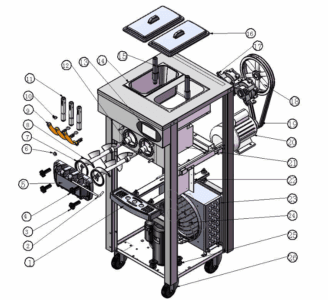
[IMAGE: Detailed technical diagram of the vertical type ice cream machine with numbers identifying each component]
No. | Name | No. | Name | No. | Name |
---|---|---|---|---|---|
1 | Water receiver | 10 | Piston seal | 19 | Belt |
2 | Stable handle pin | 11 | Piston | 20 | Stirring motor |
3 | Lower fixing nut | 12 | Bell stamp | 21 | Evaporator |
4 | Upper fixing nut | 13 | Operation panel | 22 | control Panel |
5 | Liquid outlet valve | 14 | Material cylinder | 23 | Condenser |
6 | Stirring shaft support sheath | 15 | Flushing tube | 24 | Fan |
7 | Seal for liquid outlet valve | 16 | Cylinder cover | 25 | Compressor |
8 | Agitation axis | 17 | Reducer | 26 | Wheel |
9 | Mango | 18 | Belt pulley |
II. Table-type structure diagram
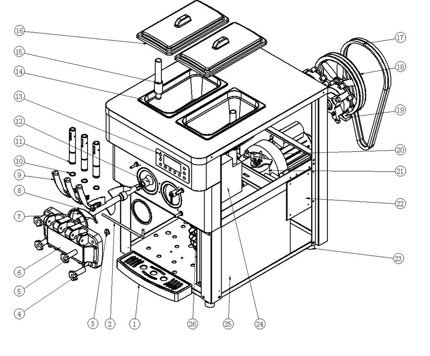
[IMAGE: Detailed technical diagram of the table-type ice cream machine with numbers identifying each component]
No. | Name | No. | Name | No. | Name |
---|---|---|---|---|---|
1 | Water receiver | 10 | Piston seal | 19 | Reducer |
2 | Stable handle pin | 11 | Piston | 20 | Stirring motor |
3 | Stirring shaft support sheath | 12 | Bell stamp | 21 | Compressor |
4 | Lower fixing nut | 13 | Operation panel | 22 | control Panel |
5 | Upper fixing nut | 14 | Material cylinder | 23 | Floor mat |
6 | Liquid outlet valve | 15 | Flushing tube | 24 | Evaporator |
7 | Seal for liquid outlet valve | 16 | Cylinder cover | 25 | Condenser |
8 | Agitation axis | 17 | Belt | 26 | Fan |
9 | Mango | 18 | Belt pulley |
4. Installation and debugging
1) Installation
a. Cut and remove the packing tape from the secured carton. Remove the carton and the packing bag to check the machine's appearance for damage and the completeness of the accessories, referring to the list.
b. The machine should be placed evenly and stably, and then firmly lock the front wheel brake.
c. Install the handle onto the liquid outlet valve according to the product structure diagram. Then install the assembled liquid outlet valve onto the machine and tighten it with the fixing nuts.
d. Working conditions:
- Ambient temperature: 5-40℃; material feed temperature: 2-35℃ (Note: The material feed temperature will directly influence the cooling capacity and output.)
- Supply voltage: 200-400v (The deviation from the rated supply voltage cannot be too high or too low. If it is too high or too low, the machine will alarm (buzz) and the machine cannot start.)
- Supply frequency: 50±1 Hz
and. Conditions of placement:
- The machine should be placed in a cool, ventilated location, avoiding heat sources and direct sunlight. The distance between the air exhaust side of the machine and walls or other similar obstacles should be greater than 1 m, and the remaining sides of the machine should be at least 0.3 m away from walls or other similar obstacles, so that cold air can flow into the machine and expel hot gas, ensuring the machine's condensation cycle.
- The machine should not be placed in a dusty location. Please keep the area clean and tidy, and regularly clean the dust from the condenser.
F. Requirements for wiring the power supply:
- Please ensure that the machine's power circuit is equipped with short-circuit and earth leakage protection devices.
- Please ensure that the power line is no shorter than 2.5mm² and is copper core wire (excluding exceptional high-power machines, which should be no shorter than 4.0mm² and copper core wire), and the power line should not be too long. When the power line is too short or too long, its load will become excessively large and cause voltage drop, thus affecting the lifespan of the machine components.
2) Debugging
a. Connect the power plug and move the power switch to the "ON" position. You will then hear a "beep" sound and the display will simultaneously turn on. The machine is now entering standby mode.
b. Press the "Wash" key, the machine enters the washing mode, and the agitation system starts working at the same time. Press the "Stop" key, and the machine will stop working.
c. Pressing the "Auto" key will start the machine, and the agitation system will begin operating at the same time. After a 10-second delay, the cooling system will also begin to operate. Press the "Stop" key and the machine will stop operating.
3) Cleaning and disinfection
When using the machine for the first time, cleaning and disinfection must be carried out carefully. The steps are as follows:
a. Take approximately 10L of warm water (40-50℃) and add an appropriate amount of food-grade cleaning solution to the water, turning it into a disinfectant. Then pour the disinfectant into the two material cylinders and allow the disinfectant to flow into the cooling cylinder.
b. Press the "Wash" button to run for 5 minutes. Lower the handle to discharge the cleaning solution.
c. Add clear water to the material cylinders and rinse 2-3 times. It's ready.
Grades:
- a. During the cleaning and disinfection process, you cannot press the "Auto" key, and you must observe the display.
- b. After cleaning, you must completely drain the water from the cylinders. Otherwise, the water will freeze in the cylinder during cooling, and the stirring shaft will be damaged.
5. Operating instructions
1) Common operation panel
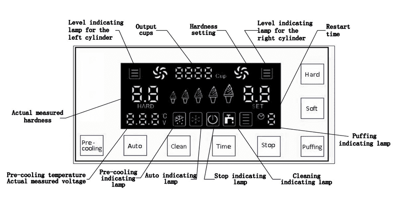
TEXTS ON THE PANEL:
Level indicating lamp for the left cylinder = Level indicating lamp for the left cylinder
Output cups = Output cups
Hardness setting = Hardness setting
Level indicating lamp for the right cylinder = Level indicating lamp for the right cylinder
Restart time = Restart time
HARD = HARD
Soft = Soft
Actual measured hardness = Actual measured hardness
Pre-cooling = Pre-cooling
Car = Car
Clean = Clean
Time = Tiempo
Stop = Stop
Puffing = Fluffing
Pre-cooling temperature Actual measured voltage = Pre-cooling temperature Actual measured voltage
Pre-cooling indicating lamp = Pre-cooling indicating lamp
Auto indicating lamp = Automatic indicator lamp
Stop indicating lamp = Stop indicating lamp
Cleaning indicating lamp = Cleaning indicator lamp
Puffing indicating lamp = Puffing indicating lamp
2) Jam operation panel
[IMAGE: Control panel similar to the previous one but with additional options for jams]
TEXTS ON THE PANEL:
Level indicating lamp for the left cylinder = Level indicating lamp for the left cylinder
Output cups = Output cups
Hardness setting = Hardness setting
Level indicating lamp for the right cylinder = Level indicating lamp for the right cylinder
Restart time = Restart time
Left jams indicating lamp = Left jam indicator lamp
Left Jams = Left Jam
Right jams indicating lamp = Right jam indicator lamp
Right Jams = Right Jam
HARD = HARD
LEFT = LEFT
Jams delay = Jam delay
Hardness setting = Hardness setting
Actual measured hardness = Actual measured hardness
Pre-cooling = Pre-cooling
Car = Car
Clean = Clean
Time = Tiempo
Stop = Stop
Puffing = Fluffing
Puffing indicating lamp = Puffing indicating lamp
Pre-cooling temperature Actual measured voltage jams delay = Pre-cooling temperature Actual measured voltage jam delay
Pre-cooling indicating lamp = Pre-cooling indicating lamp
Auto indicating lamp = Automatic indicator lamp
Stop indicating lamp = Stop indicating lamp
Cleaning indicating lamp = Cleaning indicator lamp
Key functions:
a. The "Auto" key When you press the "Auto" key, the buzzer will emit a short beep and the "Auto" indicator light will turn on. The machine enters the automatic operating state, and the stirring motor begins to operate. The actual measured hardness value displays the current current of the stirring motor. After 10 seconds, the compressor, fan, and solenoid valve begin operating, and the machine enters fully automatic mode. When the actual measured hardness reaches the set hardness, the machine will automatically stop and enter automatic standby mode. When the stop time reaches the set time, the machine will restart and repeat the same cycle. If you wish to stop the machine, simply press the "Stop" key.
b. The "Clean" key When you press the "Clean" key, the buzzer will emit a short beep and the cleaning indicator light will turn on. The machine enters the cleaning state, and the stirring motor begins to operate. The actual measured hardness shows the current stirring motor current. When you press the "Stop" key, the machine will stop operation and enter standby mode.
c. The "Time" key The reset time can be set by pressing the "Time" key. Pressing it each time increases the time by 1 minute. The higher the value, the longer the reset time. The cycle time is 3-9 minutes. After completing the setting, the time will be automatically saved after 5 seconds.
d. The "Stop" key Whether the machine is in cleaning status or automatic working status, as long as you press the "Stop" key, the machine will stop operating and return to standby status.
e. The "Pre-cooling" key When you press the "Pre-cooling" key, the pre-cooling indicator light will light up, indicating that the pre-cooling function is enabled. When the feeder temperature is above 15°C (59°F), the pre-cooling system will operate; when the feeder temperature is lower than 8°C (46°F), the pre-cooling system will shut down. You can see the actual measured temperature displayed here.
f. The "Puffing" key When you press the "Puffing" key, the puffing indicator light will light up, indicating that the puffing function is enabled. At this point, if you start the cleaning function, the puffing pump output will always be on. If the automatic function is enabled, the puffing pump will turn on for 1 minute and then shut off. If there is a tapping action, after tapping is complete, the puffing pump will turn on after an 8-second delay and shut off after working for 1 minute. Pressing the "Puffing" key again will turn off the puffing function.
g. Level indicator lamp for the cylinders When there is material in the material cylinder, the level indicator light for the cylinder will be continuously lit. When the cylinder is short of material, the corresponding level indicator light will flash and the buzzer will sound simultaneously. After feeding the material, the above phenomena may be alleviated.
h. Departure cups
- Zero cleaning of output cups Pressing and holding the "Stop" key for 5 seconds enters the zero-clearing password entry menu (the initial zero-clearing password is 8888). At this point, pressing the Plus key moves the password, and pressing the Minus key changes the password value. After correctly entering the password, pressing the "Stop" key again completes the zero-clearing of the output cups and exits.
- Zero-Clean Password Review Press and hold the "Time" key for 5 seconds. Then, you'll enter the password entry menu. Enter the initial password reset, then press the Plus key to move the password, and press the Minus key to change the password value. After you've finished resetting the password, press the "Time" key again to save the password reset and exit.
i. Hardness adjustment
- Common operation panel Press and hold the "Hardness+" or "Hardness-" button for 2 seconds, and the hardness adjustment LED will flash. You can then adjust the hardness of your ice cream. The higher the number, the harder the ice cream, and vice versa. After completing the setting, the hardness value will be automatically saved within 5 seconds.
- Jam operation panel i) Press and hold the "Hardness Setting" key for 2 seconds, and the hardness setting LED will flash. You can then adjust the hardness of the ice cream. The cycle time can be set from 4.0 to 7.0. The higher the number, the harder the ice cream, and vice versa. After completing the setting, the hardness value will be automatically saved within 5 seconds.
ii) Press and hold the "Jams delay" key for 2 seconds, the jam delay LED flashes. At this time, press the "Jams delay" key to change the value. The cycle time can be set from 0.0 to 0.9 seconds. The higher the number, the greater the jam amount when the ice cream is jammed, and vice versa (generally, the suggested value is 0.3 seconds). After completing the setting, it will be automatically saved in 5 seconds.
j. The "Jams" key
- When the machine is in the cleaning state, pressing the "Jams" key will turn on the Jam indicator light and the jam pump will start operating. When you press the "Jams" key again, the Jam indicator light will turn off and the jam pump will stop operating.
- When the machine is in automatic operation, pressing the "Jams" key will turn on the jam indicator light. Lowering the handle will activate the corresponding jam pump. Restoring the handle to the right will stop the jam pump. Only one jam pump can be started; in other words, when you start the left jam pump, the right one will automatically turn off, and vice versa. When you don't need jam, remember to turn off the "Jams" key before making ice cream.
Grades:
- a. Pre-cooling, fluffing, material shortage alarm, and jamming functions are optional, which can be added separately according to customer requirements.
- b. For machines with jam functions, remember to turn off the "Jams" key when you don't want jam. When you turn on the "Jams" key, you can simply lower the corresponding handle to do so. Otherwise, jam will flow out of the discharge hole on the other side.
6. Ice cream making method
- Currently in China, ice cream is usually made by mixing ice cream ingredients with water. Please mix them strictly according to the ratio printed on the ice cream bag (generally, 1 kilogram of ice cream ingredients should be mixed with 2.5-3 kilograms of purified water).
- Let the mixed ice cream pulp rest for 15 minutes, then pour it evenly into the two material cylinders at the top of the machine. The pulp must not clump together so that it can flow smoothly into the cooling cylinder through the feed opening of the overflow tube.
- Lower the left and right handles to allow 2-3 cups of ice cream pulp to flow naturally through the two discharge holes. Then pour it into the upper material cylinders to prevent the water from freezing in the discharge opening, as this will affect the ice cream's consistency.
- Turn on the power. When the machine enters standby mode, press the "Cleaning" key and let the machine run for approximately 3-5 minutes. After that, press the "Stop" key to stop the machine.
- Press the "Auto" key. When the machine enters the cooling and molding state, press the "Soft or Hard" key to select the desired ice cream hardness. (Note: In the pre-cleaning state, you should closely observe the current hardness value displayed. If the current value is displayed as 3.5, then the ice cream hardness should be set between 4.5 and 5.5. If it is displayed as 4.0, then the hardness should be set between 5.0 and 5.5.)
- When the actual measured hardness of the ice cream reaches the set value, the machine will automatically stop and enter standby mode. At this point, you can press the "Time" key to set the time as needed for the automatic refrigeration cycle. The automatic refrigeration cycle is set to 3-9 minutes. Pressing the key each time increases the time by 1 minute. Until it reaches 9 minutes, pressing the key again will return the machine to the 3-minute state. (Note: In hot weather, it is better to set the stop time to a shorter time, and vice versa.)
- Take an ice cream cone or cup and place it on the valve outlet. When you lower the material discharge handle, the ice cream will be extruded. After a moment, pull the handle back, and it's ready.
Grades: An appropriate amount of ice cream pulp must be ensured in the machine's material cylinders, as a shortage of material will cause damage to the stirring shaft. Frequently check that the feeding orifice of the fluffing tube is smooth to prevent blockages resulting from uneven pulp and to prevent material shortages in the freezing cylinder.
7. Maintenance and repair
To ensure the health of ice cream consumers, improve the lifespan of machine components, and avoid unnecessary problems, you should clean the cooling cylinder once a day.
1) Cleaning the cooling cylinder
toPress the "Cleaning" key to discharge all the pulp into the cylinder. Press the "Stop" key to stop the machine.
b. Add an appropriate amount of disinfectant to warm water. Then pour the mixture into the two material cylinders respectively, each containing essentially the same amount of solution.
c. Press the "Cleaning" button again and let the machine agitate for approximately 5 minutes. Then, empty the cleaning solution.
d. Clean the machine 2-3 times with clear water and then stop the machine.
and. Turn off the power supply. Disassemble the components and clean them.
F. Unscrew the four nuts used to secure the liquid outlet valves and disassemble the valve components.
g. Remove the stable pins from the handle, handle, piston and valve seal in the order of the liquid outlet valve components.
h. Remove the stirring shaft from the cooling cylinder.
Yo. Clean all disassembled components and promptly replace any damaged ones.
j. After cleaning, apply petroleum jelly to the components that need lubrication according to the following diagram. Then assemble the components in the reverse order of disassembly.
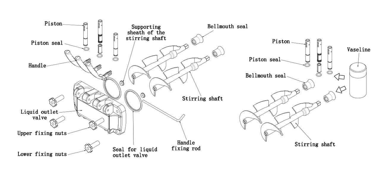
[IMAGE: Detailed diagram of the parts to be lubricated]
TEXTS IN THE IMAGE:
Piston = Piston
Supporting sheath of the stirring shaft = Vaina de soporte del eje de agitación
Bellmouth seal = Bell seal
Piston seal = Piston seal
Vaseline = Vaseline
Handle = Mango
Piston seal = Piston seal
Bellmouth seal = Bell seal
Stirring shaft = Stirring shaft
Liquid outlet valve = Liquid outlet valve
Upper fixing nuts = Upper fixing nuts
Lower fixing nuts = Lower fixing nuts
Seal for liquid outlet valve = Seal for liquid outlet valve
Handle fixing rod = Rod de fijacion del mango
Note: Apply petroleum jelly to the appropriate locations when installing pistons, piston seals, agitator shaft, and bell seals, as frequent use of petroleum jelly can prolong the life of the components.
2) Body cleansing
Since consumers demand a beautiful, clean, and sanitary machine, maintain a clean appearance at all times. You can use a warm towel to scrub the body to remove dirt and stains, but avoid washing it directly with water in case the appliance malfunctions.
3) Cleaning the condenser
After the machine has been running for a period of time, the condenser will become covered with dust, affecting heat dissipation and worsening the refrigeration effect (which manifests itself as ice cream production decreasing over time or making it difficult to shape). Please have it cleaned once every three months (if the working environment is poor, clean it once a month) by professional workers. Before cleaning the condenser, turn off the power and be careful not to damage the condenser fins.
4) Adjusting the strap
After the machine has been running for a period of time, the agitation system's drive belt may stretch, so it must be professionally adjusted in a timely manner. Before adjusting, turn off the power. Then, disassemble the housing plates to adjust the belt tension nuts and ensure proper tension. If the belt still feels too loose after adjustment, replace it with a belt of the same type.
Grades: After long periods of use, it's normal for the drive belt to wear, which is not included in our product after-sales service. When the drive belt lengthens, the following may occur: machine inoperability, changes in hardness, loud noise, rubber odor, etc. Please adjust it promptly, either yourself or have it professionally adjusted. If necessary, replace it. The timing for adjustment and replacement depends on the machine's utilization rate.
8. Common problems and their solutions
Thank you for choosing our equipment. This ice cream machine is a professional mechatronics unit, which integrates computer program control, mechanical transmission, and a high-efficiency refrigeration system. The following table shows common problems that may occur in the machine, along with their causes and solutions. Simple problems can be addressed according to the solutions listed in the table. If they still cannot be resolved, consult the dealer or manufacturer for guidance. If the problems are difficult and complex, please call in professionals for repairs.
No. | Issues | Possible causes | Solutions |
---|---|---|---|
1 | The machine cannot start | Whether the ignition switch is on or off | Turn on the ignition switch yourself |
The power line is not properly connected | Check the power line and connect it properly. | ||
The protection circuit works | Reboot the machine after fixing the problem | ||
The control board is problematic | Replace the control board | ||
2 | The cleaning function does not work | The connection line is loose | Check the connection line and connect it firmly |
The stirring motor or capacitance is damaged | Repair or replace the capacitance or motor | ||
The AC contactor is damaged | Replace the AC contactor | ||
3 | The compressor does not work | The connection line is loose | Check the connection line and connect it firmly |
The voltage is too low | Check the supply voltage | ||
The contactor is damaged | Replace the contactor | ||
The control board is problematic | Replace the control board | ||
The compressor capacitance is damaged | Replace the capacitance | ||
Compressor overload protection works | Find the causes and eliminate them | ||
The compressor is damaged | Replace the compressor | ||
4 | The cooling does not work | The coolant is leaking | Find the leak location and repair it properly. Fill the refrigerant to a vacuum. |
The solenoid valve is damaged | Replace the solenoid valve | ||
The fan does not work | Repair or replace the fan | ||
The compressor is working abnormally | Check the compressor | ||
5 | The belt slips | The belt is too loose | Adjust belt tension or replace belt |
Freezing cylinder, agitation shaft broken | Adjust the hardness and replace the stirring shaft | ||
6 | The ice cream can't come out | There is no material in the cylinder | Replace the pulp |
The sponge tube is blocked | Remove the fluffing tube and clean it. | ||
Incorrect pulp ratio, causing freezing of the cylinder | Make the pulp graded again | ||
The material discharge switch on the panel is damaged or the connection line is short-circuited. | Reconnect the line or replace the discharge switch. | ||
The belt is too loose and slipping | Adjust or replace the belt | ||
The reducer is problematic | Repair or replace the reducer | ||
The stirring shaft is worn | Replace the agitation shaft | ||
7 | Poor sponging | The sponge tube is not inserted | Reinsert the fluffing tube |
The raw material of the ice cream is of poor quality | Improve the quality of raw materials | ||
8 | After starting, electric leakage occurs | Induced electricity of the casing | Check that the power line is firmly grounded. If not, have it connected by professionals. |
9 | The ice cream is too soft | Incorrect pulp mixing ratio | Make qualified pulp again |
Improper hardness setting | Reset hardness | ||
Unstable voltage | Adjust the voltage | ||
Loose belt | Adjust or replace the belt | ||
The unloading of material is too frequent | After the actual hardness is greater than 1, make the ice cream then | ||
10 | Machine does not stop | The hardness is set too large | Adjust the set hardness down |
Poor cooling | Check the cooling system | ||
The discharge switch is damaged or the connection line is short-circuited | Reconnect the line or replace the material discharge switch. | ||
11 | Material leak | Leak in the liquid outlet valve | Replace the liquid outlet valve and lock it with the fixing nuts. |
Leak at the discharge hole | Replace the piston seal | ||
Leak in the liquid connecting pipe | Replace the bell seal and lock it with the fixing nuts | ||
Leak inside the machine | Replace the cylinder connecting tube | ||
12 | Alarm "JJ" | The stirring motor current is too high | Check belt tension, stirring motor and capacitance |
13 | "UH" Alarm | Voltage too high | Check the supply voltage |
14 | "UL" alarm | Voltage too low | Check the supply voltage |
15 | Alarm "Cb" | The material discharge switch closes in succession for more than 3 minutes | Reset or replace the material discharge switch |
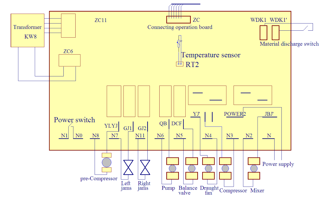
9. Electrical principle diagram
10. Attached accessories
- Stamps: 1 set
- Edible Vaseline: 1 bottle
- Liquid outlet valve: 1 set
- Handle: 3 pieces
- Water receiver: 1 set
- Cylinder cover: 2 pieces
- Stirring shaft: 2 pieces
- Fixing nuts: 5 pieces
- Fluffing tube: 2 pieces
- Instructions: 1 copy
11. Technical parameters
The specific technical parameters are shown on the machine nameplate.
If any changes appear in the instructions, please forgive us without prior notice!