
ARCMFTC900 AR10169 THREE-DIMENSIONAL DICE CUTTING MACHINE
USER GUIDE
Dear user: Before using the product, please read the product instruction manual carefully.
INDEX / TABLE OF CONTENTS
- GENERAL INFORMATION ……………………………………………………………………………….1
- STRUCTURAL CHARACTERISTICS AND OPERATING PRINCIPLE. …………….1
- MAIN TECHNICAL PARAMETERS ……………………………………………………………3
- OPERATION AND USE ……………………………………………………………………………………….3
- FAULT ANALYSIS AND ELIMINATION………………………………………………………………7
- MAINTENANCE AND MAINTENANCE:……………………………………………………………..8
- TRANSPORT AND STORAGE ……………………………………………………………… 10
1. GENERAL INFORMATION
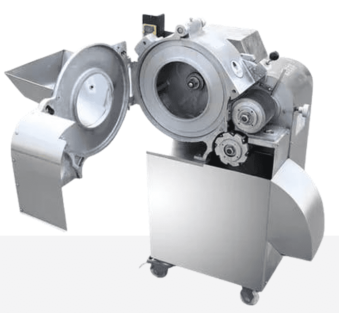
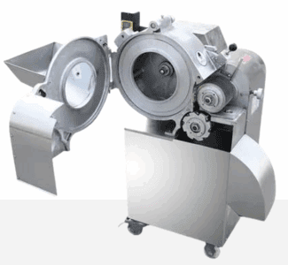
The Model 100 Dicing Machine is suitable for dicing boneless meat at approximately -6°C, as well as dehydrated vegetables, deep-frozen vegetable processing plants, and pickling industries to process various root and stem vegetables into cubes and dices. It has a regular shape and smooth cutting surface. This machine features an advanced design, convenient operation, low energy consumption, and high efficiency. It is made of aluminum alloy and stainless steel, which is corrosion-resistant and meets hygiene and certification standards.
2. STRUCTURAL CHARACTERISTICS AND OPERATING PRINCIPLE.
2.1. To know the structural characteristics,
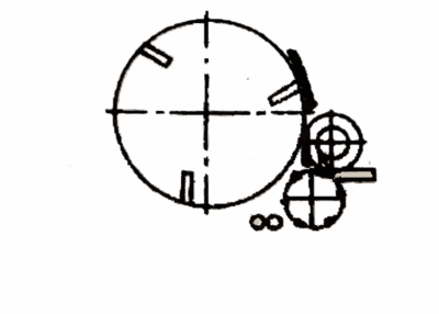
Refer to the dicing machine schematic diagram (Figure 1) and the transmission schematic diagram (Figure 2)
![]()
Numbered components:
- Housing
- Adjusting screw
- Switch
- Quadrant nut
- Adjustment plate
- Quadrant
- Adjustment frame
- Limiter
- Adjustment handle
- Eccentric handle
- Slicing knife
- Slicer blade holder
- Wire cutter body
- Setscrew
- Wire retaining plate
- Comb holder
- Fixed blade body
TEXTS IN THE IMAGE:
rotating drum = rotating drum
pot = pot
gear I = gear I
large pinion = large pinion
chain = chain
main gear = main gear
engine = motor
feed hopper = feed hopper
vertical blades = vertical blades
V-belt = V-belt
small pinion = small pinion
horizontal blades = horizontal blades
middle gear = medium gear
gear – = gear –
large V-pulley = large V-pulley
2.1.1. The machine is mainly composed of a base, a casing, a dial, a vertical blade, a horizontal blade body, a horizontal cutting blade body, a transmission system, and an electrical control system.
2.1.2. The frame, casing, hopper and main parts of the machine are made of aluminum alloy and stainless steel to ensure long-term operation without corrosion and toxicity.
2.2. Operating principle
The dial of this machine drives the object to be cut to rotate at high speed, and the centrifugal force of the object cuts the object into slices with the help of force. It then cuts it into strips through the disc shredder blade and sends the material to be cut onto the horizontal cutting edge. The cross-cutting blade cuts it into the required cubes. (Figure 3, schematic diagram of dicing)

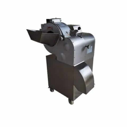
Dicing Machine for Small Diced Ham or Frozen Meat and Chicken 5mm to 15mm
6.333,66$ Taxes included
TEXTS IN THE IMAGE:
support plate = support plate
upper door = upper door
adjustment lever = adjustment lever
fixing bolts = fixing bolts
pot = pot
adjusting screw = adjusting screw
support plate = support plate
4.2.4.2. Disc shredder blade replacement: The replacement disc shredder combination blade has different specifications, such as 5 mm and 10 mm, and other specification combination blades can also be customized according to needs.
[TABLE: Figure 5 – Pitch of vertical disc cutting blades]
| Cutting thickness | Passing of pieces |
|---|---|
| 5 mm | 5 mm |
| 10 mm | 10 mm |
Combined disc shredding cutters of various specifications are standard accessories and can be customized according to needs.
Replacing Sized Blades. Replacement steps: First, loosen your grip, push the handle down so that the micro-cut combination blade emerges from the comb. Then, loosen the nut at the end of the shaft, hook the slot at the front end of the combination tool with a hook wrench, remove the combination tool, and replace it with the required size combination tool. Tighten the nut at the end of the shaft. Move the handle up to observe whether the transmission gear inside the machine is properly meshed. If the meshing is correct, the handle will be close to the controller, and the shredded blade from the disc will enter the groove of the comb and the vertical blade. There is no friction between the upper blade and the comb and vertical blade. If it jams, tighten the handwheel and complete the replacement. (Figure 6)
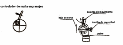
TEXTS IN THE IMAGE:
gear mesh controller = gear mesh controller
lever of movement = lever of movement
cutting blade = cutting blade
security screw = security screw
comb = comb
4.2.4.3. Replacement of Combination Cutting Tools for Cross Cutting. Depending on the cutting length and the requirements of the material to be cut, different types of combination cross-cutting knives are selected. Combination cross-cutting knives come in two specifications: 8-blade and 15-blade. Blades of other specifications can also be customized according to requirements, and the dimensions corresponding to the cutting length are as follows:
Cross section and grade The number of slices in the cut group:
- 5 mm: 15 sheets
- 10 mm: 8 sheets
4.2.5. The comb is used to scrape the residual material compressed between the vertical blades. When the comb is installed, the blade edge must be close to the surface of the blade spacer (it must not touch the vertical blades, otherwise it may damage the comb) combined with the horizontal blades to cut the perfect dado.
The position of the comb (adjust the calibration value of the scale line 5mm, 10mm, 15mm) must be consistent with the set slice thickness, otherwise it will affect the machine performance and slicing quality.
4.2.5.1. Incorrect installation, the material cannot pass through and the comb knife 11 is not close to the surface of the spacer ring of the combined disc and the shredding cutter. (Figure 7-1)
4.2.5.2. Incorrect installation: the comb blade edge is in contact with the septum ring, and the ring surface is damaged. The comb may be bent or broken. (Figure 7-2)

5. FAULT ANALYSIS AND ELIMINATION
Error table
| Symptom | Cause analysis | Solution method | Observations |
|---|---|---|---|
| Inefficient Operation | V-belt too loose, Slipping while working | Tighten the regular V-band | |
| The material does not fall correctly | 1. Knife edge comb With spacer The ring distance Too large.<br>2. The slice thickness is too thick | 1. Replace the comb, the position of the comb has to be closer to the blade ring.<br>2. Adjust the first cut (slice) blade | |
| The material is not cut | 1. The direction of rotation of the dial is different<br>2. The comb is clogged<br>3. The combined blade with the disc cutter<br>4. The vertical blade is blocked by material | 1. Adjust the rotation of the rotating disc clockwise.<br>2. Clean the comb.<br>3. Check that the blades are correct and that they are securely fastened to the lathe.<br>4. Clean the remaining material on the vertical blade | POINTS 2. AND 4.<br>If the product has a high fat content, it is recommended to remove excess fat. Otherwise, the product should be kept at a low temperature to prevent clogging. (Frozen) |
| When the material does not appear constantly or in fibers or with chipping phenomenon | 1. The blades are loose<br>2. The cutting discs are worn | 1. Adjust the cutter and cutting disc. Check the comb clearance to 1 mm.<br>2. Check the condition of the discs and their sharpness (if they are in poor condition, it is advisable to replace them) | Ground cutting disc figure 10 |
6. MAINTENANCE AND MAINTENANCE:
All maintenance and servicing work must be carried out after cutting off the power supply.
6.1. The machine must be cleaned after each use, especially the area and passageway where the material passes. (MANDATORY)
6.2. After each use, carefully check whether all cutter blades are damaged or dull, check whether the comb blade edge is normal or damaged, disassemble the disc shredder combination blade and horizontal cutter combination blade once a week (be careful when disassembling, use special tools to avoid hurting your hands) and clean them properly. When reassembling, they must be maintained with non-toxic and odorless food-grade oil, and food-grade oil must be applied to the shredding shaft and cutter shaft before installation to ensure easy disassembly.
6.3. Gear and chain oil every two weeks.
6.4. Grinding of various knives:
6.5. 1 Polishing and installation of vertical blades
To sharpen the vertical blade, on the disc wire cutter side only, sharpen edge 1 with oilstones at angle (a). When the mouth damage can be corrected Within 4 mm, the method can be to grind the gap area Angle (B) to form a new edge at angle (a). In addition, the edge is close to the side of the turntable, and the slight arc formed on the inside of the cutting edge is of the required shape to facilitate the operation of the cutting material. (As shown in Figure 8, schematic diagram of Vertical Knife Grinding.)
TEXTS IN THE IMAGE:
high angle of incidence = high angle of incidence
polishing this surface = polishing this surface
rotating disk = rotating disk
disc cutting blade = disc cutting blade
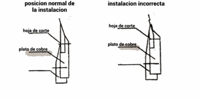
Move the lower end of the arc toward the top of the knife tray, as shown on the left side of Figure 9, but do not collide with the turntable. However, when the lower end of the arc is lower than the top of the turntable, it must be adjusted upward, otherwise it will not be possible to cut. (Figure 9 vertical knife installation schematic.)
TEXTS IN THE IMAGE:
normal installation position = normal installation position
incorrect installation = incorrect installation
cutting blade = cutting blade
copper plate = copper plate
6.5. Grinding disc shredder blades
When grinding round wire-cutting blades, to ensure a uniform blade diameter, mechanical grinding must be used; manual grinding is prohibited. The grinding direction (the direction of the tool being ground) must be inclined toward the center. The disc grinder blade may only be used until the diameter is reduced by 6 mm (see Figure 10, Schematic diagram of disc wire-cutting blade sharpening).

TEXTS IN THE IMAGE:
both sides of the blade are polished = both sides of the blade are polished
the width is 3mm = the width is 3mm
6.6. Grinding of cross-cutting blades
6.6.1. When the damage to the cutting edge of the cross-cutting knife is small, less than 2.5 mm (when it is greater than 2.5 mm, the entire blade must be replaced), the upper edge of the cutting edge is polished on the grinding machine or oilstone by mechanical or manual means. (Figure 11).

6.6.2. When disassembling the cross-cutting blade, if the screw cannot be loosened, soak the entire combination blade in hot water and the screw will be easy to loosen.
7. TRANSPORT AND STORAGE
7.1. During the use of the product, it is strictly prohibited to knock, tilt, and invert, so as not to damage the machine and affect the use.
7.2. For long-term use, the product should be stored in a dry, non-corrosive gas environment and should not be in contact with corrosive substances to avoid damage to the product.