
Ultrafiltration machine instruction manual ARDLF8-40
Operation Manual – Ceramic Membrane Filter (ARDLF8-40)
CONTENT
- Safety precautions
- Components
- PID and 2D drawing
- System operation
- Use and maintenance
- Troubleshooting
- Appendix
Read this operating manual before performing any operation.
I: Components
1. Component List
| Item No. | Name | Specification | Material | Amount |
|---|---|---|---|---|
| I. Filter | ||||
| 1 | SS casing | DQSH-301200-3 | SS304/316 | 2 pcs |
| 2 | Membrane element | CM3019041200/20nm | ceramics | 6 pcs |
| II. Pump (explosion-proof motor) | ||||
| 1 | CADLF8-40 | 1.5kw | SS304/316 | 1 pc |
| III. Tank | ||||
| 1 | Cleaning tank | 100L | SS304/316 | 1 pc |
| IV. Instruments | ||||
| 1 | Flowmeter | Concentrate: 1.6-16m³/h / FI01 | SS304/316 | 1 pc |
| 2 | Flowmeter | Permeate: 40-400L/h / FI02 | Glass | 1 pc |
| 3 | Pressure gauge | 0-1MPa / PG01,PG02 | SS304/316 | 2 pcs |
| 4 | Temperature meter | 0-150℃ / TG01 | SS304/316 | 1 pc |
| V. Valve System | ||||
| 1 | Filter valve | V01-02 | SS304/316 | 1 lot |
| 2 | Cleaning valve | CV01-03 | SS304/316 | 1 lot |
| 3 | Permeate valve | PV01-04 | SS304/316 | 1 lot |
| 4 | Drain valve | DV01-04 | SS304/316 | 1 lot |
| 5 | Pressure adjustment valve | FV01 | SS304/316 | 1 pc |
| 6 | Vent valve | VV01 | SS304/316 | 1 pc |
| 7 | Sampling valve | concentrate+permeate | SS304/316 | 2 pcs |
| VI. Control System | ||||
| 1 | control Panel | Explosion proof | 1 pc | |
| 2 | Accessories | 1 set | ||
| VII. Pipeline System | ||||
| 1 | Security filter | Style Y | SS304/316 | 1 pc |
| 2 | Heat exchanger | 0.5m² | SS304/316 | 1 pc |
2. Ceramic Membrane Module
2.1 3 elements/SS housing; 2 housings in series 2.2 Ceramic membrane element:
| Item No. | Specification | Pore size |
|---|---|---|
| DARQCM30-19-4*1200mm | OD: 30mm ID: 4mm Channel: 19 Length: 1200mm | 20nm |
2.3 Membrane element assembly: (see appendix 5: membrane assembly instruction)
3. Control Panel
- 3 phase, 220V, 60HZ, Explosion proof (see appendix 1: terminal diagram for CMF3-2/M)
II: PID and 2D drawing
(see appendix 2: PID diagram/process appendix 2: 2D drawing)
III: System Operation
1. Operating Conditions
| Item | Description | Parameter | Item | Description | Parameter |
|---|---|---|---|---|---|
| Membrane area | 0.286m2 * 6 | Min. circulation volume | 40 L | ||
| Working temperature | 5-80℃ | pH | 0-14 | ||
| Working pressure | 0—4bar | Work environment | interiors |
2. System Control
- Pressure regulation: FV01
- System control panel: start/stop button NOTE: It is prohibited to close FV01 to 100%.
3. Pre-Start Check
3.1 Check liquid level in circulation/cleaning tank (minimum: 40L) 3.2 Check power supply and pure water supply 3.3 Check if pressure regulating valve (FV101) is fully open 3.4 Check if all other valves are closed 3.5 For first use, vent air in pump: When pump is full of liquid, start pump, loosen pump air vent bolt (in the middle of pump body) to vent air, then tighten vent bolt. But because your ethanol concentration is too high, you do not need to vent air.
4. Operation Process
4.1 System flushing 4.2 Filtration process 4.3 Cleaning process 4.4 Drainage process
NOTE:
- Dry running of the pump is prohibited
- Forbidden to close FV01 to 100%
- For its ethanol filtration, VV01 can be kept closed
Before starting:
- connect your own tank to the system (with V01,V02) as a circulation tank
- Connect PV03 to your permeate tank
- connect drain valve to your drain pipe
4.1 System Flush (same as 4.3 cleaning process)
For first use or long term storage (more than 72 hours), the system should be rinsed with pure water before filtering. Open Y-style safety filter and remove solids.
- The permeate flow rate under a pressure (recommended outlet pressure/post-membrane pressure: 1 bar) should be recorded as a normal criterion for the pure water flow rate.
4.2 Filtration Process
1): Open: FV01(100% open), V02, PV02, PV03, finally open V01; all other valves keep closed.
2): Start P01, when the system works stably (5-20 minutes), adjust FV01 to suitable working pressure (1-4bar before membrane) and get a higher and stable permeate flow rate, (record this flow rate and pressure as normal criterion for source liquid flow rate). then filtration process begins.
3): When filtration stops, close all valves (except FV01).
NOTE:
- During filtration, fresh liquids must be fed into the circulation tank to maintain the liquid concentration volume.
- If no more fresh liquids are added, with the increase of concentration in the circulation tank, the permeate flow rate will become lower and lower. When the permeate flow rate becomes much lower than the normal criterion (recorded in 4.2), slowly open the pressure regulating valve (FV01) until fully open, then stop the pump.
4.3 Cleaning Process
(see appendix 4: cleaning instruction)
Note: The system must be cleaned when a filtration batch is completed.
1): Open: FV01(100% open), CV02, PV02, PV04, finally open CV01; all other valves keep closed.
2): Start P01, when the system works stably (5-20 minutes), adjust FV01 to suitable working pressure (1-4bar before membrane) and get a higher and stable permeate flow rate, then the cleaning process begins.
3): When cleaning stops, close all valves (except FV01).
4.4 Drainage Process
Filtration drain: 1): Open: FV01(100% open), V02, PV02, PV03, VV01(if necessary), DV01, DV02, DV03, DV04, all other valves keep closed.
2): When the drainage is finished, close all valves (except FV01).
- Do not forget to close VV01 if it is open during drainage.
Cleaning drain: 1): Open: FV01(100% open), CV02, PV02, PV04, VV01(if necessary), DV01, DV02, DV03, DV04, all other valves keep closed.
2): When the drainage is finished, close all valves (except FV01).
- Do not forget to close VV01 if it is open during drainage.
5. Cleaning Agent Selection
If the membrane element is seriously contaminated, depending on the nature of the feed material, the following cleaning agents can be chosen:
- Acid Cleaner: 1~3%HNO3, 1%H3PO4, Oxalic Acid, 112°F(50°C)
- Caustic Cleaner: 1~3%NaOH, Na3PO4, NaClO, 112°F(50°C)
- Chelating Agent: EDTA
- Surfactant: SDS
- Enzymatic Agent: Amylase, Protease
Please refer to Appendix 7: Cleaning Instruction for detailed cleaning process.
When the flow of the membrane element cannot meet the production capacity demand, the membrane element must be replaced.
6. Membrane Element Assembly
(see appendix 5: membrane element assembly)
7. Membrane Element Storage
Short term (up to one week): pure water Long term: 1% w/w sodium sulfite or 1% w/w H2O2
7.1 Short-term storage shutdown
Short-term storage is applicable to cases when the shutdown is 1-7 days and the membrane elements are still installed in the system.
Storage steps are: After cleaning the system with pure water to neutral, fully ventilate the air and fill the system with pure water, store membrane elements in the system for next work.
7.2 Long-Term Storage Stoppage
Long-term storage is applicable to the case when the stoppage is more than 7 days.
The storage steps are:
- After system cleaning, remove the membrane elements from the system, store the elements in 1% w/w sodium sulfite or 1% w/w H2O2
- Install the elements back into the system every 1-3 months, and clean with pure water or 1~3% NaOH solution for 30min, then clean with pure water until neutral
- Then take out elements again and store them in the freshly prepared 1% w/w sodium sulfite or 1% w/w H2O2
IV: Use and Maintenance
Please read this operation manual carefully. Any incorrect operation may damage the membrane equipment or even cause personal injury.
- Operation of the pump without liquid is prohibited
- Try to vent the air in the pump
- Temperature and pressure gauges in the system should be checked regularly
- During work, no air must enter the system.
- The parameters obtained from each operation, such as concentrate flow rate, permeate flow rate, membrane inlet/outlet pressure, temperature, should be recorded.
- The next operation step can only be performed after the pump works stably.
- Valves that are open during work must not be closed until the pump has stopped completely.
- When adjusting FV101 (pressure regulating valve), the pressure must not exceed 6 bar
- To avoid rapid contamination of the membrane, it is forbidden to close FV101 completely.
- The maximum working pressure should not exceed 6 bar, and the speed over the membrane should be controlled between 3-5 m/s
- If the flow rate can meet the production capacity, the working pressure should be as low as possible to reduce the contamination rate on the membrane surface.
- In case of any accident during work, the accident should be resolved only after draining all the fluids in the system.
- The system should be cleaned immediately once the drain is complete.
- A suitable cleaning agent must be chosen for different contaminants.
- After complete cleaning, if the permeate flow rate cannot be recovered well or cannot meet the production capacity, the ceramic membrane elements should be replaced.
- When the ambient temperature is lower than 5℃, the equipment cannot be used, and the liquid in the system must be drained to prevent the equipment from being damaged.
- If the equipment is not working for more than three months, it should be stored away from direct sunlight, dust, corrosive gas, combustible gas, steam, oil mist, vibration and salt environment etc, it should be cleaned regularly referring to “III 7.2 long-term shutdown storage”.
V: Troubleshooting
Classification Description Cause Solution System failure System cannot boot Power phase is not correct single phase Power is not connected Connect the power The voltage is not suitable Check the power supply Defective circuit or poor contact Check circuit or contacts Drain Loose clamp or flange Reset Damaged seals Replace seals Pump failure Abnormal sound, abnormal vibration, pump pressure gauge pointer fluctuates; Pressure does not rise Loss of power phase Check energy Stamps are worn out Replace seals Air in pump not vented Vent air into the pump Pipe leaks, air sucked in Check suction pipe Loose base Tighten the base bolts Pump works in opposite direction Adjust power supply System failure Permeate flow rate lower or falls System pressure is too low Adjust regulating valve to increase system pressure Feed temperature is too low Raise the temperature Feed concentration is very high Decrease concentration Contaminated element Chemical cleaning Permeate is cloudy Membrane element is damaged Replace membrane element Leaking seals Reassemble or replace seals Bubbles No need to treat VI: Appendix
- terminal diagram
- PID/process diagram
- 2D drawing
- DQCM cleaning instruction
- membrane element assembly
- experimental record sheet
Appendix 1: Terminal Diagram for ARDLF8-40
Technical Specifications
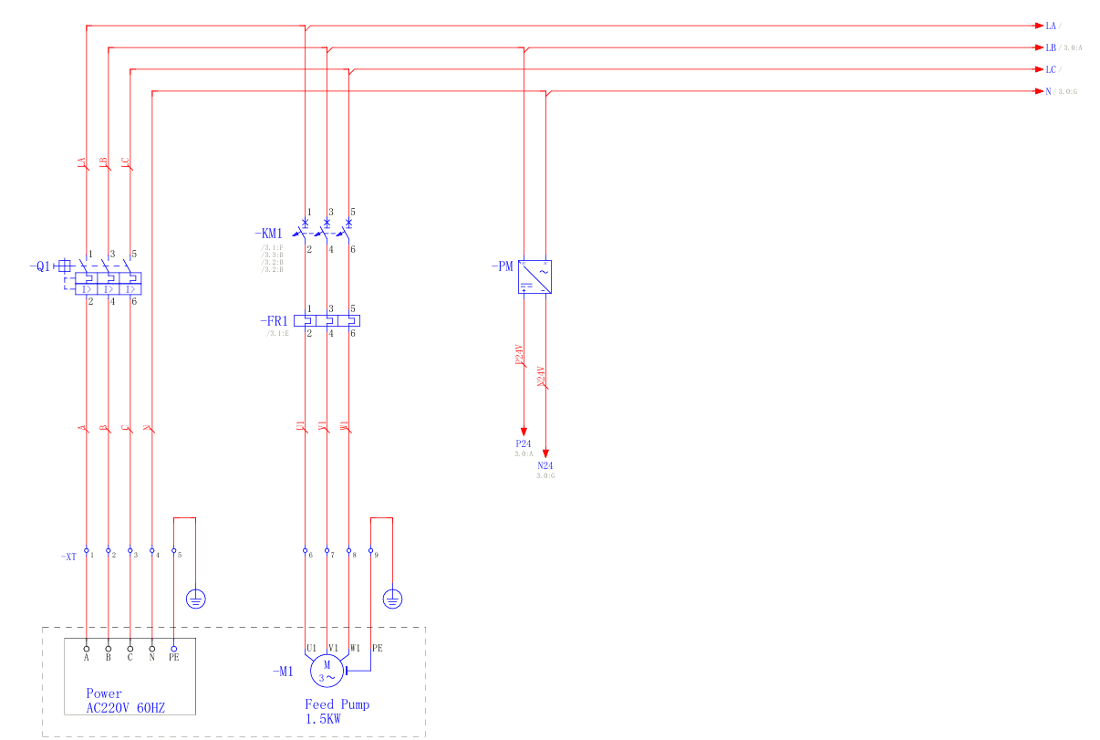
- Project Name: ARDLF8-40
- Voltage: AC220V 60HZ+N+PE
- Drawing Number: DCC

Terminal Connection Table (XT)
| Terminal | Internal Cable | External Cable | Page | Function |
|---|---|---|---|---|
| XT1 | -Q1:2 | TO | /2.0:H | Power AC220V 60HZ |
| XT2 | -Q1:4 | B | /2.1:H | |
| XT3 | -Q1:6 | C | /2.1:H | |
| XT4 | -P.M | N | /2.1:H | |
| XT5 | PE | PE | /2.1:H | |
| XT6 | -FR1:2 | -M1:U1 | /2.2:H | Feed Pump 1.5KW |
| XT7 | -FR1:4 | -M1:V1 | /2.3:H | |
| XT8 | -FR1:6 | -M1:W1 | /2.3:H | |
| XT9 | PE | -M1:PE | /2.3:H |
Important Notes on the Electrical System:
- The system includes a main power supply circuit
- Low voltage power distribution
- Connections for 1.5KW feed pump
- Control system with integrated protections
- All connections must be made following the specified color and numbering code.
The feed pump features:
- Explosion proof motor
- Overload protection
- Start/stop control system
- Operation and stop indicators
Appendix 2: PID / Process Diagram

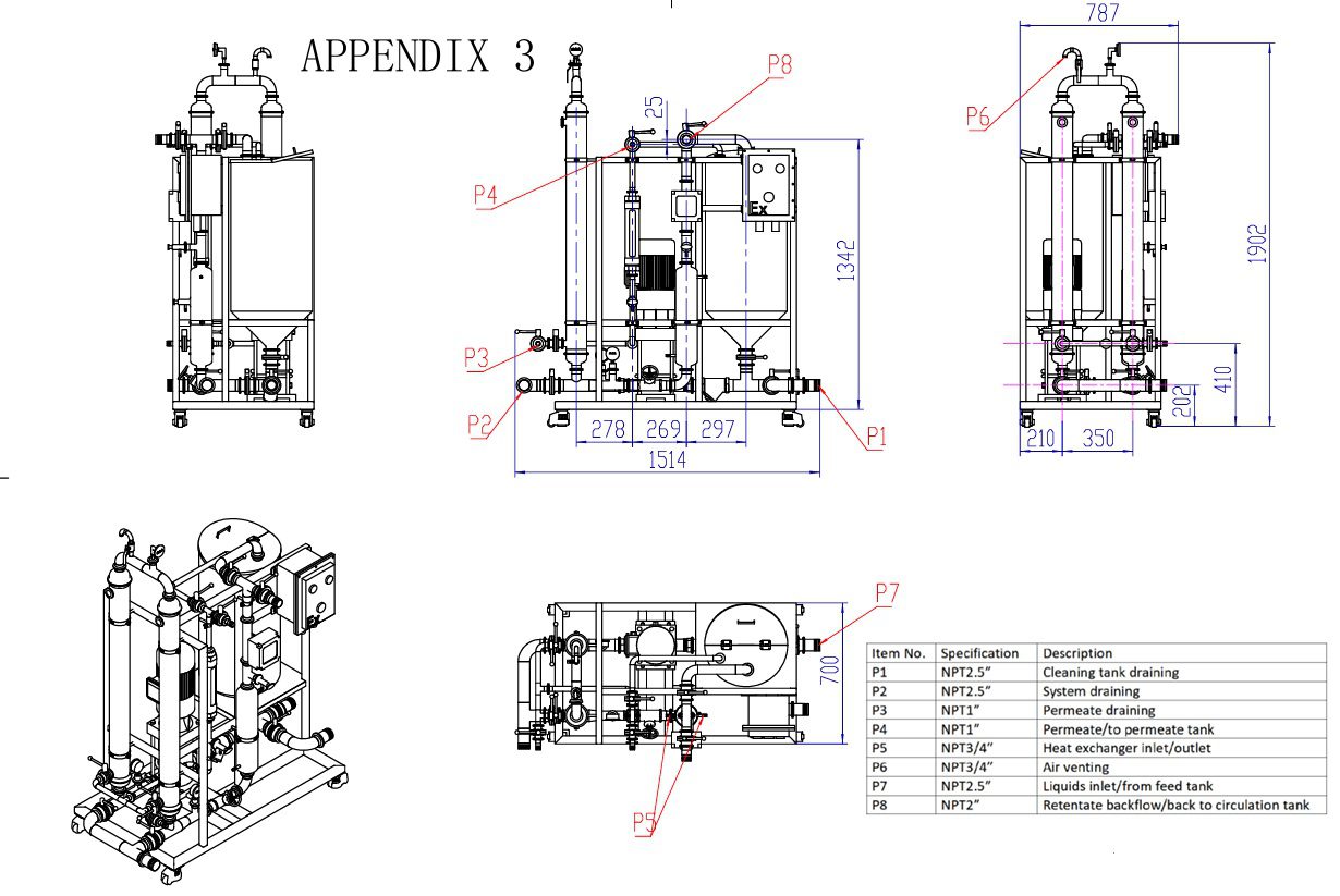
Appendix 3: 2d Drawing
Connection Specifications Table
| Item No. | Specification | Description |
|---|---|---|
| P1 | NPT2.5″ | Draining the cleaning tank |
| P2 | NPT2.5″ | Draining the system |
| P3 | NPT1″ | Permeate drainage |
| P4 | NPT1″ | Permeate/to permeate tank |
| P5 | NPT3/4″ | Heat exchanger inlet/outlet |
| P6 | NPT3/4″ | Air ventilation |
| P7 | NPT2.5″ | Liquid inlet/from feed tank |
| P8 | NPT2″ | Retentate return/return to circulation tank |
Main Dimensions
- Overall height: 1902 mm
- Width: 787 mm
- Base length: 1514 mm
- Base details:
- 278mm + 269mm + 297mm = 1514mm (total length)
- 210mm + 350mm (side dimensions)
- Height from ground: 40 mm
The drawing shows three different views of the system:
- Front left view
- Front view with dimensions
- Front right view
- Isometric view (3D perspective)
- Side view
This technical plan is essential for:
- Installing the equipment
- Space planning
- Identifying connections
- System maintenance
Appendix 5: Membrane Assembly Instructions with Conical Seals
Necessary Materials
- Inner hex key
- Conical seals
- Housing gasket
Step by Step Procedure
Preparation Phase
- Preparation of Materials
- Gather inner hex key
- Conical seals
- Housing gasket
- Surface Preparation
- Place the case on a flat wooden board or soft cloth
Element Installation Phase

- Installing the First Element
- Seal one end of the membrane element with the conical seals
- Insert the element into the hole in the housing
- Ensure that both ends of the element protrude the same length on both sides of the housing
- Full Installation
- Insert all membrane elements into the housing one by one
Sealing Phase
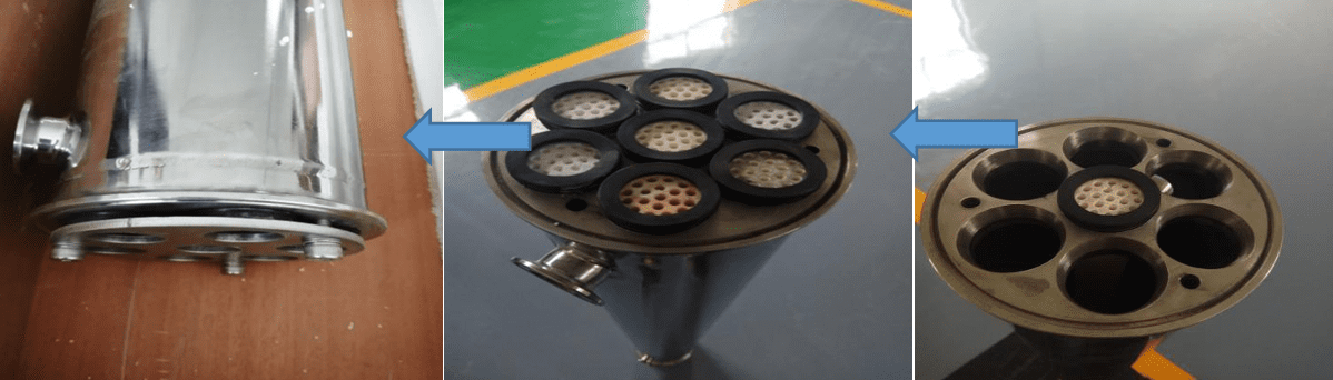
- First End Sealing
- Cover the end of the housing with the plate
- Secure with inner hexagon bolt
- Second End Sealing
- Flip the case over
- Insert the conical seals
- Fix the plate
Final Phase
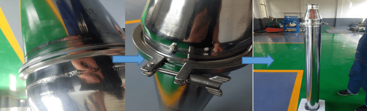
- Installation of the Board
- Place the housing gasket into the gasket groove
- Final Assembly
- Fix the reducer at both ends of the housing with the clamp
Important Notes
- Ensure all connections are tight
- Check that the conical seals are properly seated
- Check that the elements are aligned evenly
- Perform a final visual inspection of all joints and connections